
 Deutsche Version
DCC Decoder v3: Buck converter
As a follow-up to my post about the DCC decoder, let me present the newest version of the decoder. It looks mostly similar, but there are important differences as well:
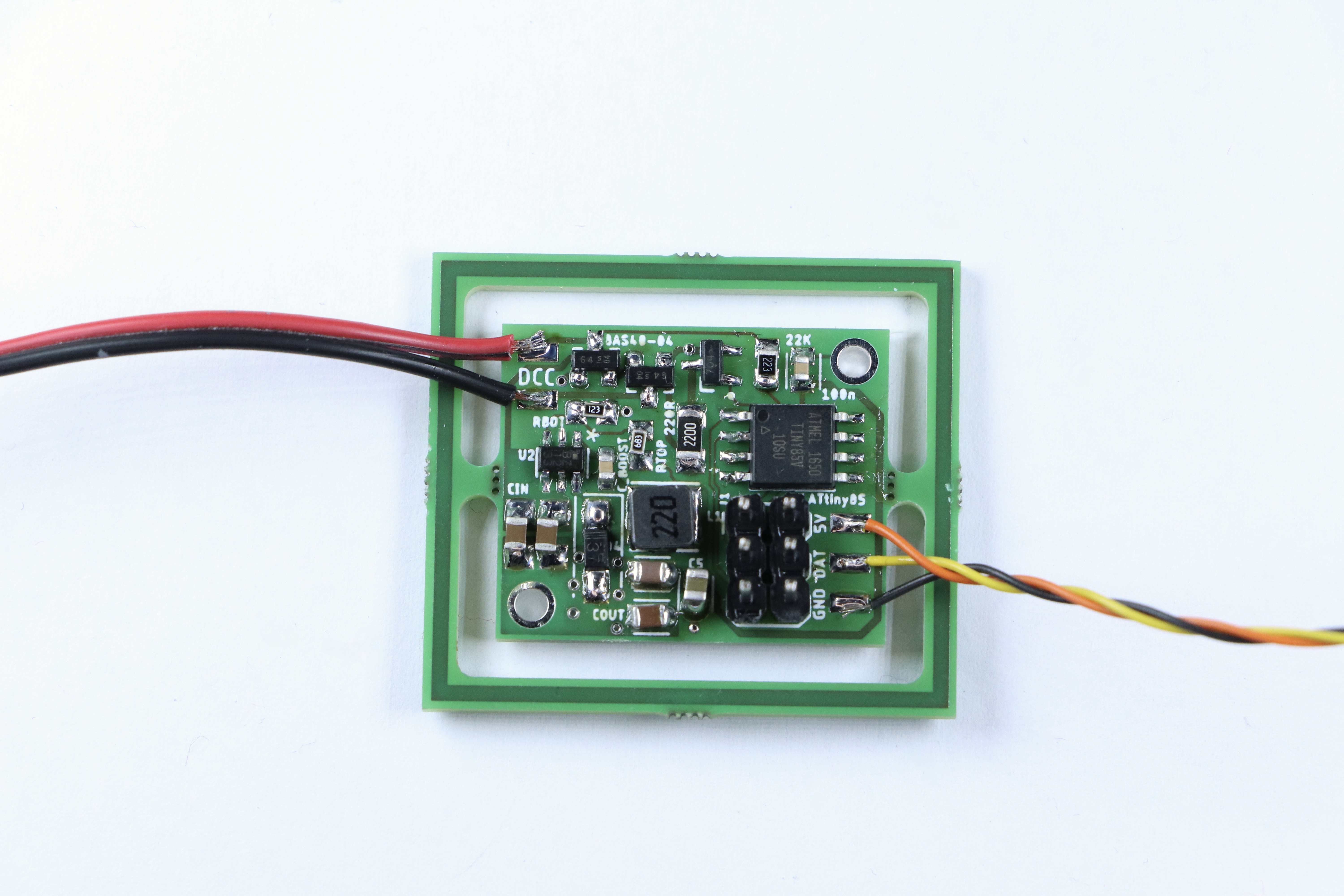
The frame on the outside isn’t a change, that’s just how the circuit board is delivered. In the pictures of the old one I had just removed it. But besides that, there are actual changes, even if it looks the same and runs the exact same software.
Let’s start by going through the changes at the upper edge:
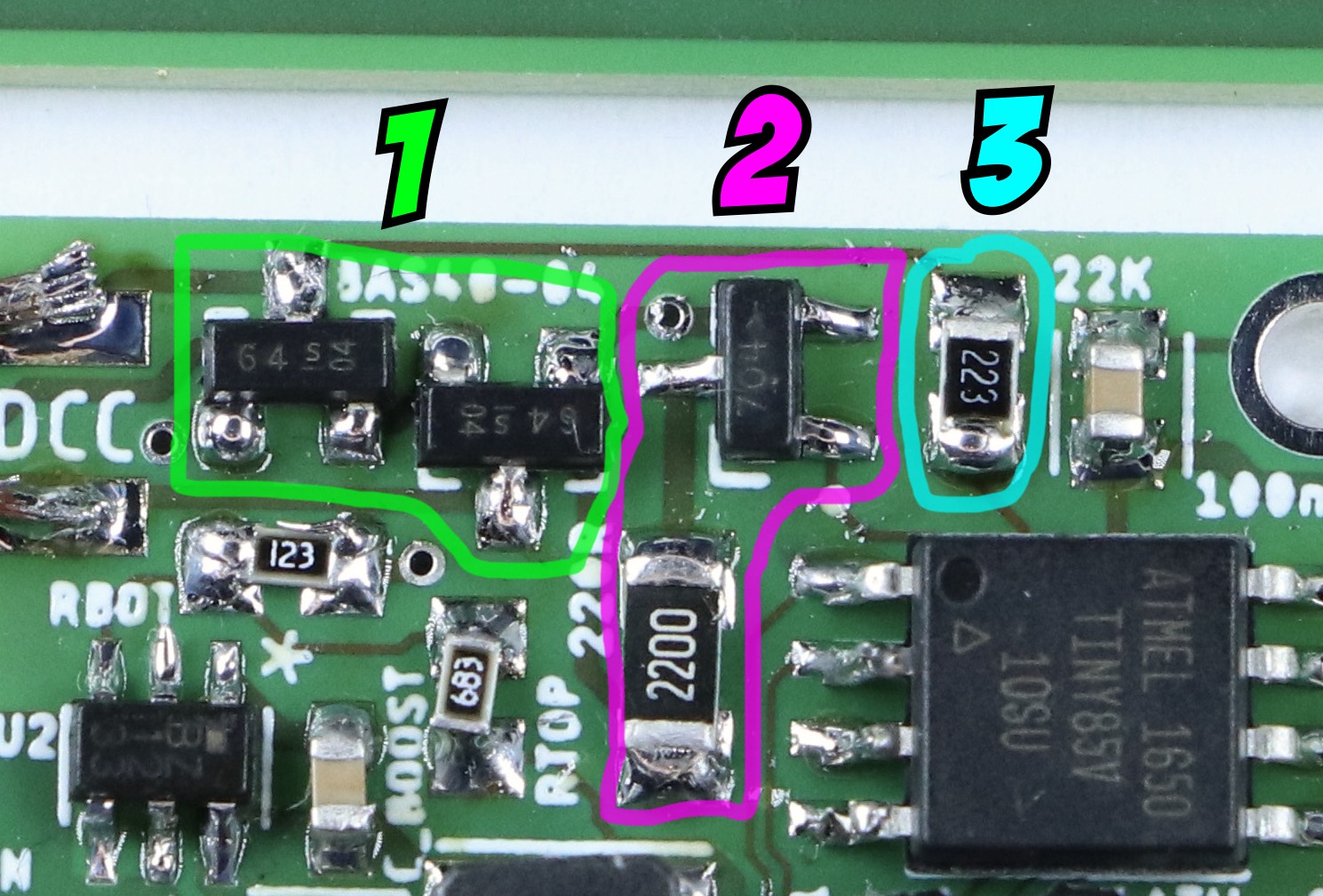
- The rectifier diodes are rearranged to take up less space.
- The transistor and resistor used to communicate back by increasing power consumption have moved.Also, the value of the resistor is now 220 Ohm, because it is now directly connected to the 15-to-25 Volt output of the rectifier, instead of the 5 Volt regulated power supply. I’m not entirely sure anymore why I did it differently before. But now it will only work this way due to how I’m generating the 5 Volt power here.
- As mentioned before, the Zener diode is gone and there’s just a single 22 kOhm resistor at the DCC input line.
And that brings me to the main part: The way I turn 15 to 25 Volt DC into 5 Volt DC is completely different.
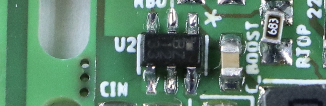
The core of the new design is a switching voltage converter called Roh BD9G102G. It’s small, essentially a six pin version of the package used for the diodes and the transistor, but it can do a lot. However, it needs a lot of external components to work correctly.
(Aside: Rohm calls this package an SSOP6, but it has the exact same dimensions as an SOT23-6, which is the “official” six pin version of the SOT23 used by the diodes and transistor. No idea why there are these two different names. Both SSOP6 and SOT23-6 are, by the way, 0.3 mm wider than the normal three-pin SOT23.)
The basic design of this power regulator is completely different than the linear regulator used in the previous design. As mentioned there, that linear regulator can be thought of as a self-adjusting resistor, that ensures that for any given current, it always sucks up exactly so much voltage that the end voltage to ground is 5 Volts DC. That’s rather inefficient; the difference voltage times the current just gets turned into heat.
In contrast to this, a switching regulator (specifically a so called buck converter) is first and foremost a switch and some logic to turn it on or off. It is always part of a circuit that also contains a diode, an inductor coil and a capacitor. It works like this:

First the switch closes. The full 15 to 25 Volts (this regulator can deal with up to 42 Volts) is now present at the input of the coil, while the diode is blocking. A current can now flow into the coil. Thanks to its self-induction, the voltage at the end rises only very slowly. At the same time the output capacitor is loaded.
Once the voltage at the coil output exceeds the target (say here 5.05 Volt), the switch opens. Now the coil and capacitor are supplying the power that is stored in them to the load. The diode conducts now, to close the loop. During this phase, the voltage will slowly drop. Eventually the switch closes, and the whole deal starts again. How often this happens depends on the regulator in question. The one I have here has a frequency of one Megahertz.
The advantage of this design is that it will supply more continous current on the output of the coil than goes into the switch on average. The concept does not rely on any power getting turned into heat. Of course some losses are inevitable, but this regulator can, under the right conditions, still reach efficiencies of more than 90%. In my use case, I’ve seen the whole decoder and LED use about half as much current as before.
To do all this, a lot of parts and pieces are needed. Here’s all of them:
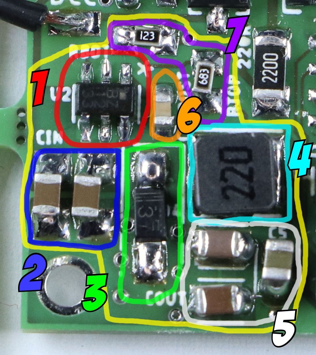
The converter is number 1 here, and the core of the design. The important pins are input (bottom center), switch output (bottom right), Ground or minus (top center), and feedback for measuring the voltage at the end of the coil (top left). Top right is “boost”, whatever that is, and bottom left is “enable”, which I could use to turn the converter off, e.g. if I had a design where it supplies something that I don’t need all the time.
The two capacitors at the input (number 2) ensure that there’s always enough current available to flow through the switch, and to supply the internal logic of the regulator. According to the datasheet, one would have been sufficient, but since DCC power can sometimes cut out, I decided to take two.
Next to it is the diode (number 3), which closes the loop when the switch is open. Next to that is the coil (number 4), the one part with the labelling that is the most easy to read in normal light, even though it’s black on gray. I’ve been using a lot of extra lights for this photo.
Even so, the labelling is misleading: The last digit isn’t part of the number, it’s the exponent, or the number of zeroes you need to add to the number. 220 does not mean 220 µH, it means 22. That it means µH and inductivity at all is something you just have to learn by heart, it doesn’t say so anywhere. Other labelled components use the same logic, for example the resistors: 123 means 12 kiloohms (not that you can actually read that without a magnifying glass), and 2200 means 220 Ohm. The capacitors, on the other hand, are not labelled at all, which feels almost refreshingly honest.
Below the coil are the output capacitors (number 5), which stabilize the power, especially if the coil is empty. Once again I probably overdid it; one should be sufficient, but this way I know I’ll never have too little capacitance.
Directly next to the regulator is the boost capacitor (number 6). I don’t know what it does. The datasheet says “Add a 100 nF boost capacitor there”, so I did. It’s connected between the switch output and a dedicated “boost” input.
Above and to the right are two resistors, which form a voltage divider. This chip is an adjustable version, which can output a wide variety of voltages. You need to build such a voltage divider to ensure that the feedback pin of the regulator gets exactly 0.75 Volts when the output voltage matches your target. You could also make this field adjustable by using a potentiometer here.
Adjustable sounds better, but honestly, for me, it’s just annoying. Non-adjustable regulators (no matter what type) are really just adjustable regulators with these resistors already built in. Sadly, this type is not available in a fixed version. (For bonus points: Any “fixed” regulator can be adjusted by adding such a voltage divider anyway, if you really want to, for some reason.)
I would have actually preferred using a regulator that doesn’t require additional resistors here, and maybe even already includes the diode. Those exist, for example the Texas Instruments LMR50410 series, but they have a problem: I can’t get them. If I order now, the earliest I’ll get one is the middle of march. That’s the case for a lot of components right now, in particular the newer fun ones. The main advantage of the Rohm BD9G102G isn’t what it does, there are quite a few similar components; it’s that I can actually get it. Or at least I could two weeks ago; right now no dealer seems to have them in stock (though at least it would only take until october to get more), so it’s a good thing I ordered enough of them. The chip crisis is very real.
This is ultimately all there is to it with this converter. Just for fun, here’s the overall circuit diagram:
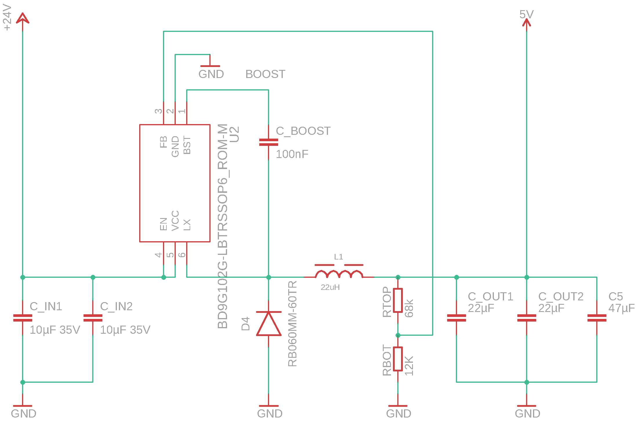
An important with all of these regulators is that they are much more delicate parts and much more delicate circuits than linear regulators. The data sheet for any switching regulator will always come with fairly precise advice for how to design your circuit board. You don’t want any part of it to become an antenna and generate electrical interference with its high frequencies. Otherwise this could disturb your circuit or others around you (e.g. distort radio signals). All the copper wires on the board and the capacitors can also start oscillating if you’re unlucky, and generate weird voltage spikes. That means proper circuit board layout and using the correct capacitors, diodes and so on is really crucial. My exaggerated input and output capacitors are things that I wasn’t actually certain would work. At the end of the day, if you just follow the advice in the data sheet, it should work well, and it did so here. Still, I’m very relieved that it worked on first try.
Written on September 22nd, 2021 at 05:38 am